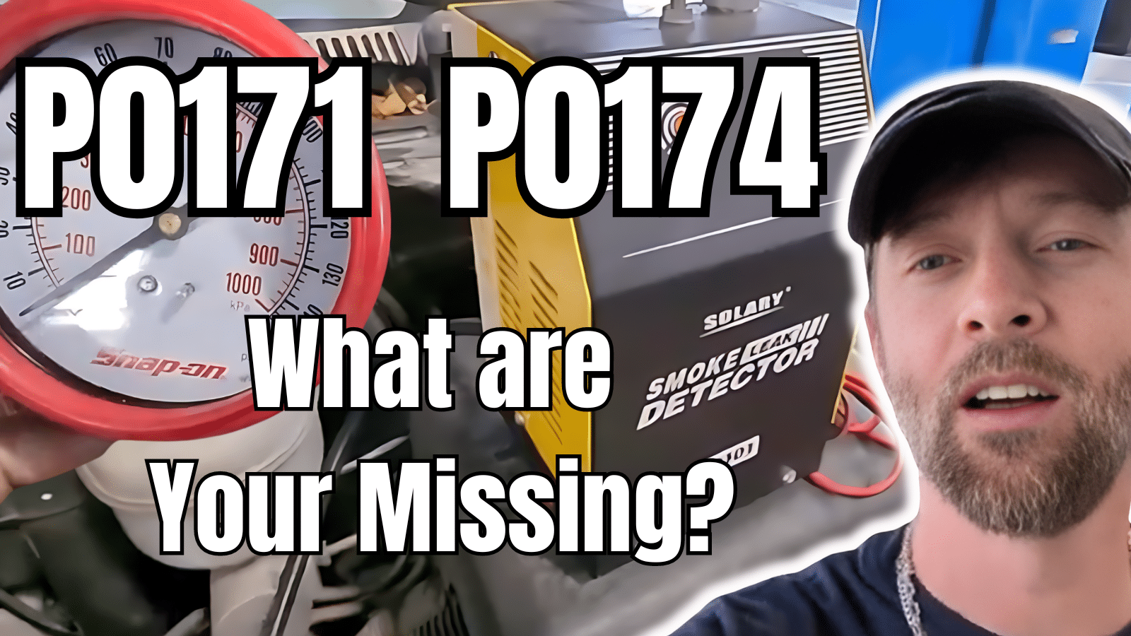
I’m going to go over some common issues causing the P0171 and P0174 error codes in Chevy and GM vehicles, indicating a system too lean in both Bank 1 and Bank 2.
Under standing fuel trim numbers can aid greatly in get to the source of the problem. We start by conducting a smoke test on the intake to detect any leaks. Next, we assess the condition and performance of the mass air flow sensor and fuel pressure test to ensure they meet specifications.
Further inspections include the PCV valve and the brake booster, along with other critical components like fuel pressure regulator, that could lead to a lean-running engine.
Whether you’re a DIY enthusiast looking to understand more about your vehicle or a professional mechanic honing your skills, this video provides step-by-step guidance on diagnosing and fixing lean engine problems and understanding fuel trim reading on a scanner.
Subscribe to my youtube channel here: https://goo.gl/j1pCfn For the most common automotive fixes to the most common car and truck problems. DIY auto repair to help you save money. Connect with me:
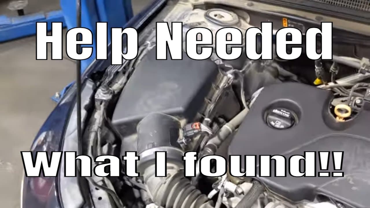
All right flat rate mechanic here again and we’re diagnosing a p1101 for airflow volume on this Chevy Malibu which seems to be a pretty common problem. The customer came in and they had already replaced the mass airflow sensor one of my techs diagnosed it and we ended up cleaning the throttle body and putting in a map sensor. The check engine light still came back on so I’m gonna kind to go through what I found and how to check these first. What you really need to do if you’re trying to fix p1101 for the airflow is you’re going to need to smoke the actual boost side of this intake system so basically you’re going to have to block off where the air comes in here and lock it off here and you’re going to want to check for leaks through this uh through the turbo through the intercooler and see if you got any leaks on that air charge side of this whole system there’s any leaks whatsoever it’s going to cause that p1101
we did smoke that we took it up here we actually smoked it through here blocked this off we didn’t find any leaks so that all checked out good and we’ve replaced both the booth sensor and the mass airflow sensor or the map sensor sorry the only sensor we haven’t done is a boost sensor but thus far that seems to check out our right but I’m going to show you what we found um I do have this little deal here wants us to check some some of the perimeters on the scan tool which I have up right now we got our boost pressure sensor fuel trim manifold pressure and mass airflow so um and on here one of the first things it wants you to do is uh we want you to basically compare your boost pressure sensor to your Maps sensor pressure so we can go ahead and do that and you’re going to want to do that with the engine off so we’ll go ahead and shut the engine off and we’ll go to English here so we’ve got pounds and you can see where uh relatively close to win range we got 13.5 and 14.1 so I would consider that acceptable so now we’ll go ahead and start it the next thing he wants us to do is check the mass airflow sensor we should have approximately three grams per second at idle so we’re going to go ahead and check that next we’re going to go ahead and start it up and we’ll change our scan tool to metric so we can read grams per second and looks like we’re at about 2.8 and now this is a new Point 2.4 actually so this is a new mass airflow sensor our idle uh seems like we are idling very low we did do a throttle body cleaning Subscribe to my youtube channel here: https://goo.gl/j1pCfn
For the most common automotive fixes to the most common car and truck problems. DIY auto repair to help you save money. Connect with me:
Check out The Flat Rate Mechanics Tool Store on Amazon https://goo.gl/M8MpdC For Promotional offers, consulting, training, sponsorships or other inquiries contact me at FlatRateMechanic1@gmail.com
The Flat Rate Mechanic. 26-year ASE Master Automotive Technician and Advanced level ASE certified here to help you save money on your automotive repairs The Flat Rate Mechanic is a participant in the Amazon Influencer Program. Disclaimer: Due to factors beyond the control of The Flat Rate Mechanic, it cannot guarantee against unauthorized modifications of this information or improper use of this information. The Flat Rate Mechanic assumes no liability for property damage or injury incurred as a result of any of the information contained in this automotive repair video. The Flat Rate Mechanic recommends safe practices when working on cars or trucks with power tools, automotive lifts, lifting tools, jack stands, electrical equipment, blunt instruments, chemicals, lubricants, or any other tools or equipment seen or implied in this repair video. Due to factors beyond the control of The Flat Rate Mechanic, no information contained in this automotive repair video shall create any express or implied warranty or guarantee of any particular result. Any injury, damage, or loss that may result from improper use of these tools, equipment, or the information contained.
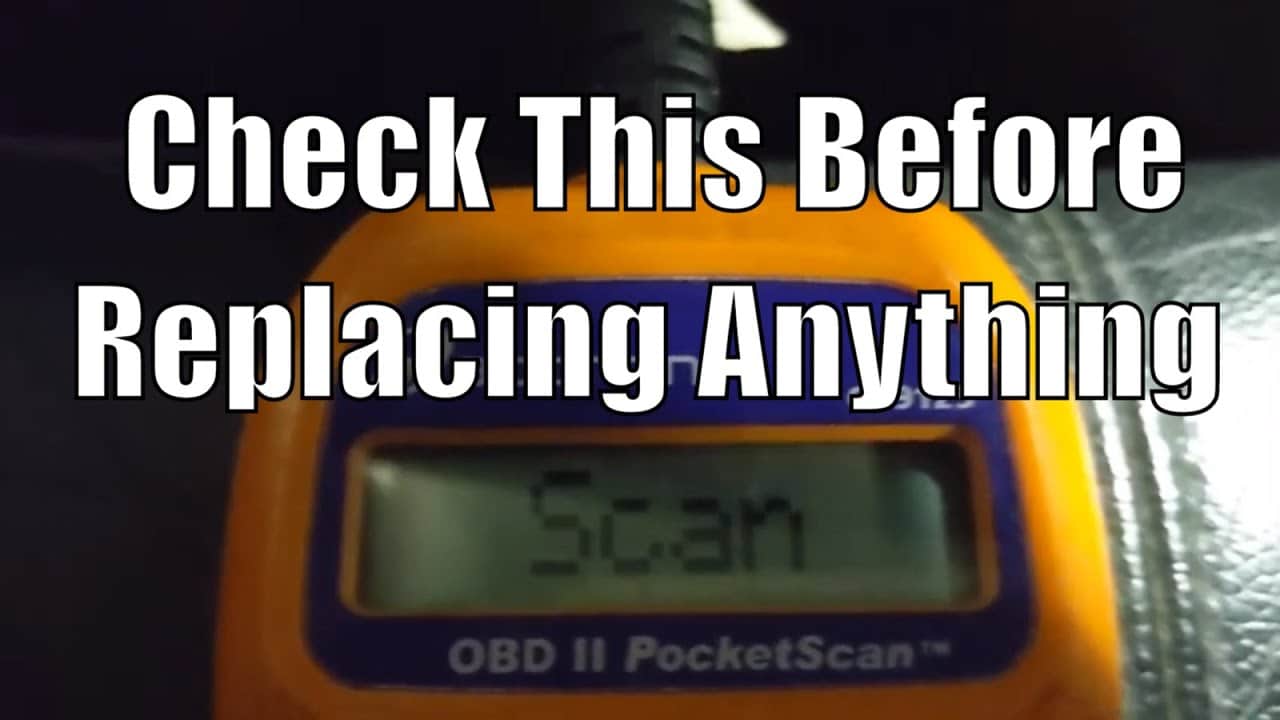
P0140 P0138 Code Chevy Truck, If you have a P0140 or a P0138 code in your chevy truck this video is for you. I will be showing you a few things you should check before replacing the oxygen sensor in your Chevy truck. Both these codes p0138 and p0140 are both for the bank 1 sensor 2 O2 sensor.
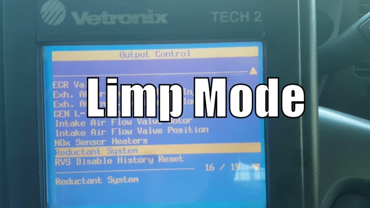
And this video we are working on a Duramax with a poor exhaust fluid quality message on the dash and the vehicle has gone into limp mode. This video is a diagnostic overview of what we did to fix the poor exhaust fluid quality message and get the vehicle out of limp mode.
We also had coolant temperature codes along with some glow plug codes. I will show you how to do a reductant fluid quality test along with a service Regen with the factory Tech 2 scan tool.
Subscribe to my youtube channel here: https://goo.gl/j1pCfn For the most common automotive fixes to the most common car and truck problems
How to remove a broken oil dipstick tube that is broken off inside of the block. And this video I have over several methods and tricks that may help in the process of getting a broken oil dipstick tube out of the engine block. I’m working on a Chevy pickup truck with a 5.3 L engine.
This method also applies for Chevy trucks with a 6.0 liter. First I had to remove the inner Fender to gain access to the oil dipstick tube. Once I had the inner Fender and tire removed I was able to get the torch in there and heat up the block to try and help the O-ring on oil dipstick tube to make it easier to remove.
Then I proceeded by using a self-tapping screw to screw into the old dipstick tube. Only the first half came out so I was unable to find another self-tapping screw to pull the second half of the dipstick out. I had to move it back and forth inside the engine block several times before I was able to remove it due to rust buildup. If for some reason the old part of the oil dipstick does fall down in the oil pan it should not cause any issues but definitely should be removed if possible.
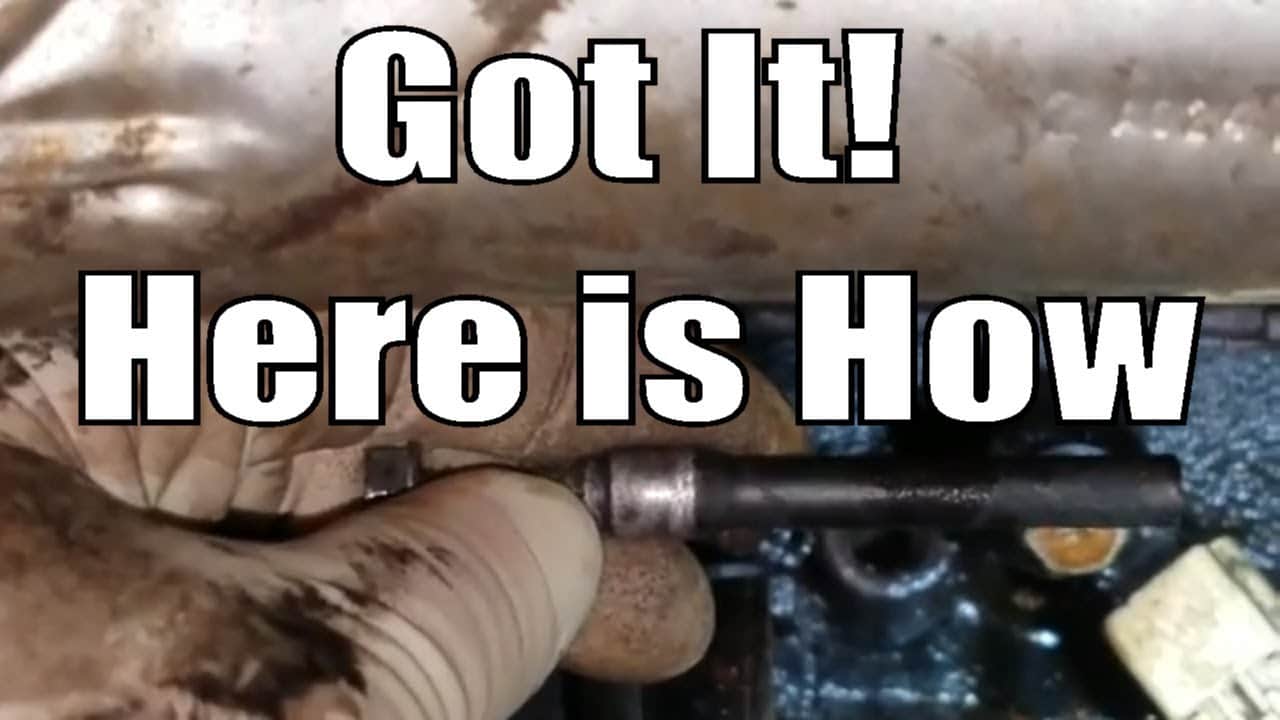
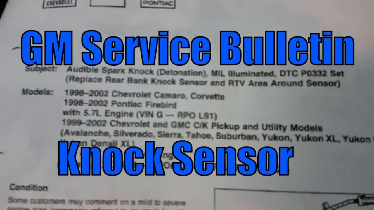
If you’re working on a Chevrolet truck and you’ve encountered diagnostic trouble codes P0332 and P0327, there’s a good chance you’re dealing with a problem related to the knock sensors. These sensors are responsible for detecting engine knock or detonation and sending signals to the engine control module (ECM) so that the ignition timing can be adjusted accordingly. In this article, we’ll explain what can cause these codes to set, what the repair entails, and what the service bulletin is recommending to prevent future failures of the knock sensors.
What Causes Knock Sensor Codes P0332 and P0327 to Set?
There are several reasons why the knock sensors on a Chevrolet truck may fail, but the most common cause is a problem with the wiring or connections. Over time, the wires that connect the knock sensors to the ECM can become corroded or damaged, which can cause the resistance in the circuit to change. This can cause the ECM to receive incorrect signals from the sensors, resulting in the engine running poorly or setting diagnostic trouble codes.
Another common cause of knock sensor failure is a problem with the sensors themselves. The sensors can become damaged or worn out over time, which can cause them to lose their ability to detect engine knock. This can also result in the ECM receiving incorrect signals and setting diagnostic trouble codes.
What Does the Repair Entail?
The repair for knock sensor codes P0332 and P0327 will vary depending on the specific problem you’re dealing with. However, in most cases, the first step will be to disconnect the blue powertrain control module (PCM) connector and check the resistance value on the light blue wire at pin 11 for sensor two and the dark blue wire at pin 51. Both should be on the blue PCM connector, and the value should be between 93K and 107K ohms.
If the resistance is low, the next step will be to check the circuit for a shorted wire or a shorted sensor. This typically involves checking the wires for damage or corrosion and testing the sensors for continuity.
If the resistance is high, the next step will be to check for a corroded wire or a poor connection at the knock sensor. This will typically involve checking the wires for damage or corrosion and inspecting the connections for signs of wear or damage.
The next step is to use an AC voltmeter and check the Hz on each wire listed above while tapping on the engine block. You should be careful not to tap on any plastic engine components. While tapping on the block, the frequency on the meter should go over 125 hz.
Finally, if the problem is a faulty sensor or damaged wiring, the repair will typically involve replacing the knock sensors and/or repairing the damaged wiring.
What Does the Service Bulletin Recommend to Prevent Future Failures?
The service bulletin for knock sensor codes P0332 and P0327 recommends that technicians use a specifically designed harness with the knock sensors. This harness is designed to provide a secure and reliable connection between the sensors and the ECM, which can help to prevent problems with resistance and continuity.
In addition to using the correct harness, the service bulletin recommends that technicians use dielectric grease on the connectors to help prevent corrosion and damage. This grease can help to protect the connectors from the elements and prevent damage from moisture, dust, and other contaminants.
Average Reported Mileage: 338036
Tests/Procedures: 1. Disconnect the Blue Powertrain Control Module (PCM) connector and check the resistance value on the Light Blue wire at pin 11 for sensor two and the Dark Blue wire at pin 51. Both of these should be on the Blue PCM connector. The value should be 93K to 107K ohms.
2. If resistance is low, check the circuit for shorted wire or shorted sensor.
3. If resistance is high, check for corroded wire or poor connection at the knock sensor.
4. Use an AC voltmeter and check the Hz on each wire listed above while tapping on the engine block.
5. While tapping on the block, the frequency on the meter should go over 125 hz.