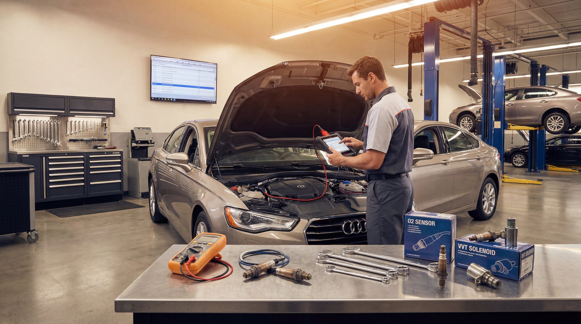
Look, one of the most common things I see people do is just start throwing parts at their car when the check engine light comes on. They’ll swap an O2 sensor, then a cam actuator, then another sensor, and basically just keep guessing until either the problem goes away or they give up. The thing is, you don’t have to guess. Today I’m gonna walk you through exactly how to figure out which sensor you actually need to replace, and more importantly, how to identify which bank and which position it’s in. Trust me, this is gonna save you a ton of time and money.
Understanding Bank 1, Bank 2, and Cylinder Identification
Alright guys, so the first thing you need to know is how to identify Bank 1 and Bank 2 on your engine. This is super important because all your sensor codes and locations reference these banks.
Here’s the deal: **cylinder one is always going to be the most forward cylinder on your engine**. On a V6 or V8 engine, whichever side has cylinder one, that’s your Bank 1. The opposite side is Bank 2. Real simple.
So if you’re looking at the engine I showed in the video, the most forward cylinder is right there on the driver’s side. That means the driver’s side is Bank 1, and the passenger side is Bank 2. But here’s the thing – this can flip depending on which way the engine sits in the car. Some cars have the engine mounted differently, so Bank 1 might be on the passenger side. That’s why you gotta know where cylinder one is, not just assume.
🔧 Pro Tip
If you have an inline engine (like a straight-four or inline-six), you only have Bank 1. All your sensors are on Bank 1 because there’s only one cylinder head. This makes things way easier.
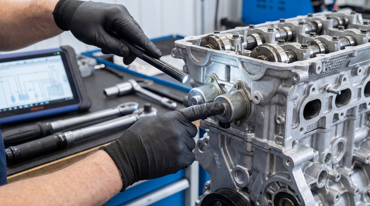
Now, once you know your banks, you need to understand intake versus exhaust. On a DOHC engine (dual overhead cam), you’ve got an intake side and an exhaust side on each cylinder head. The intake is where air comes in, exhaust is where it goes out. Pretty straightforward, but you need to know this for identifying VVT solenoids.
Real quick, let me break down VVT solenoids – or variable valve timing solenoids. These things control your cam phasers and adjust valve timing. On most modern engines with dual VVT, you’re gonna have four of these solenoids total on a V6 or V8.
Here’s how it breaks down:
– **Bank 1 Intake VVT** – Controls intake cam timing on Bank 1
– **Bank 1 Exhaust VVT** – Controls exhaust cam timing on Bank 1
– **Bank 2 Intake VVT** – Controls intake cam timing on Bank 2
– **Bank 2 Exhaust VVT** – Controls exhaust cam timing on Bank 2
So when you pull a code that says “Bank 2 Exhaust Cam Position Actuator Circuit,” you know exactly which one to look at. You go to Bank 2 (remember, that’s the side WITHOUT cylinder one), and you find the exhaust side solenoid. Boom, done.
4
VVT SOLENOIDS
on most modern V6/V8 DOHC engines
The thing is, these solenoids look identical. You can’t just eyeball them and know which is which. You have to trace back from the intake and exhaust cam positions. According to industry repair resources, VVT solenoid failures are super common on 2005–2025 model year vehicles, especially once you get past 100k miles. Usually they get clogged with sludge or the screen inside gets dirty.
💰 Money Saver
Before you replace a VVT solenoid, try cleaning it first. Pull it out, spray it with brake cleaner, and blow it out with compressed air. Check the little screen filter on the inlet side. If it’s just dirty and not mechanically damaged, cleaning it might save you $50-150 per solenoid.
Locating Oxygen Sensor Positions (Upstream vs Downstream)
Now let’s talk O2 sensors, because this is where people get confused all the time. You’ll see codes like “Bank 1 Sensor 1” or “Bank 2 Sensor 2,” and you need to know what that means.
Here’s the breakdown:
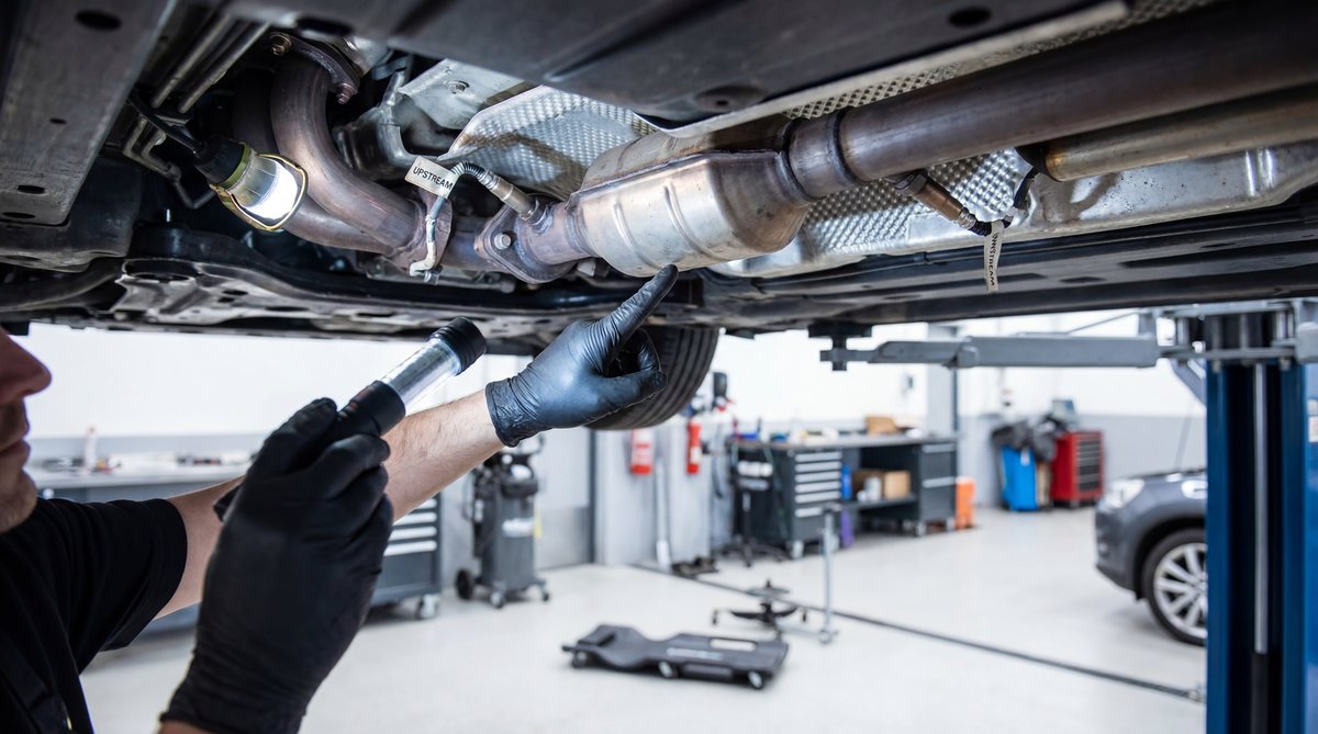
**Bank 1 Sensor 1 (B1S1)** – This is your upstream O2 sensor on Bank 1. It’s gonna be screwed into the exhaust manifold or right after it, before the catalytic converter. This sensor controls your fuel trim, so it’s constantly switching voltage to tell the computer if you’re rich or lean.
**Bank 1 Sensor 2 (B1S2)** – This is your downstream O2 sensor on Bank 1. It’s after the catalytic converter. This one mainly monitors cat efficiency, so it should read pretty steady if your cat is working right.
Same deal for Bank 2 – you’ve got an upstream (Sensor 1) and a downstream (Sensor 2).
So basically, Sensor 1 is always upstream, Sensor 2 is always downstream. Real simple once you know the pattern.
Sensor 1 is always before the cat, Sensor 2 is always after. Upstream controls fuel trim, downstream monitors cat efficiency.
Flat Rate Mechanic
On a typical V6 or V8, you’re looking at four O2 sensors total – two upstream (one per bank) and two downstream (one per bank). Some vehicles have even more if they have multiple cats, but that’s the basic setup for most cars from 1996 on up.
⚠️ Warning
Exhaust components get ridiculously hot – we’re talking 600-800°F or more. Never try to remove or test O2 sensors with the exhaust hot. Let the car sit for at least an hour after running before you touch anything on the exhaust. Seriously, I’ve seen guys get second-degree burns from this.
If you’re dealing with misfires along with sensor issues, you might want to check out our guide on testing ignition coils too, since ignition problems can throw off your O2 sensor readings.
How to Actually Diagnose Which Sensor Is Bad
Alright, here’s where most people go wrong. They pull a code, Google it, order the part, and slap it in. But here’s the thing – **a trouble code tells you where to look, not what to replace**. You still gotta actually test and confirm the sensor is bad.
Let’s say you pull a P0141 code – that’s “O2 Sensor Heater Circuit Malfunction Bank 1 Sensor 2.” What do you do? First, you go look at Bank 1 Sensor 2 (the downstream sensor on the Bank 1 side). Then you:
1. **Check the wiring and connector** – Look for corrosion, damaged pins, or broken wires. A ton of sensor codes are actually wiring problems, not bad sensors.
2. **Check live data** – Hook up a scan tool and watch what the sensor is actually doing. An upstream O2 sensor should be switching between about 0.1 and 0.9 volts multiple times per second when the engine is warm and running. According to O2 sensor diagnostic procedures, if it’s stuck high or stuck low, or switching super slowly, it’s likely bad.
3. **Test the heater circuit** – Most O2 sensors have a heater element to get them up to operating temp faster. You can test this with a multimeter. Should see low resistance (usually 5-20 ohms) across the heater terminals.
🔧 Tools Needed for Sensor Diagnosis
OBD-II scan tool with live data capability
Digital multimeter
Wiring diagram for your vehicle
O2 sensor socket (22mm offset socket for most)
Penetrating oil (for stuck sensors)
Anti-seize compound (for reinstall)
For VVT solenoids, the diagnosis is similar. You pull a code like P0011 “Intake Cam Position Timing Over-Advanced Bank 1.” Now, that could be the VVT solenoid, but it could also be:
– Low oil level or wrong oil viscosity
– Clogged oil passages
– Stretched timing chain
– Bad cam phaser (the actual actuator on the cam)
So what we’re gonna do is check oil level first, then command the VVT solenoid with a scan tool and see if the cam timing actually changes. If you command it and nothing happens, and you’ve verified good oil pressure, then yeah, probably the solenoid or the phaser itself.
❌ Common Mistake
People see a cam timing code and immediately replace the VVT solenoid without checking oil level. I’ve seen this a dozen times. The oil was just two quarts low, but they spent $80 on a solenoid they didn’t need. Always check the basics first – oil level, oil condition, and service history.
The point is, you don’t just throw parts at it. You use the code to figure out which system and which bank, then you actually test that specific sensor or component to confirm it’s bad.
DIY Diagnosis & Repair
Shop Cost
You Save
$50-150 (parts + tools)
$300-600
$250-450
Common Mistakes That Cost You Money
Let me tell you about the mistakes I see all the time, because this stuff adds up fast.
**Mistake #1: Guessing which sensor based on the code alone.** Like I said, a P0420 “Catalyst System Efficiency Below Threshold” doesn’t automatically mean you need a new cat or O2 sensor. Could be a vacuum leak, could be a misfire, could be an exhaust leak. Test before you replace.
**Mistake #2: Not using anti-seize on O2 sensor threads.** When you install a new O2 sensor, you gotta put a little anti-seize on the threads (avoid getting it on the sensor tip though). If you don’t, that thing is gonna be welded in there by corrosion next time you need to change it. Then you’re drilling and retapping, and the whole job goes sideways.
**Mistake #3: Mixing up the banks.** Seriously, this happens more than you’d think. Guy replaces the Bank 2 sensor when the code said Bank 1, then he’s confused why the light came right back on. Take your time, identify cylinder one, figure out your banks, and double-check before you start wrenching.
🔧 Pro Tip
Take a photo of the sensor location and connector before you disconnect anything. That way when you go to reassemble, you know exactly how it was routed and clipped. This saves time and prevents you from accidentally unplugging the wrong connector.
**Mistake #4: Ordering parts by looks instead of VIN.** O2 sensors and VVT solenoids might look the same across different model years, but the wiring, thread pitch, or software calibration can be different. Always look up parts by your VIN or exact year/make/model/engine code. Don’t just grab something off the shelf because it looks right.
**Mistake #5: Ignoring safety stuff.** Disconnecting the battery is not optional when you’re working on sensors. You can short circuits, fry modules, or even get shocked. And like I said earlier, exhaust stuff gets hot – wait for it to cool. Also, if you’re gonna be under the car for O2 sensors, use jack stands, not just a jack. Real basic safety, but guys still skip this and end up hurt.
⚠️ Warning
If you’re seeing multiple cam timing codes along with rattling or chain slap noises on startup, do NOT just replace sensors. You might have a stretched timing chain or failing chain tensioner, which is a way bigger job. Have it inspected by a pro before you start replacing sensors – you could be missing a major mechanical problem.
And one more thing – if your car is still under powertrain warranty, check before you DIY. Some warranty companies will deny a claim if they find out you replaced sensors yourself, even if you did it right. Just something to keep in mind.
Frequently Asked Questions
What are the most common symptoms of a faulty engine sensor?
Alright, so the symptoms really depend on which sensor is bad. For O2 sensors, you’ll usually see the check engine light come on, poor fuel economy, rough idle, or a rotten egg smell from the exhaust. For cam position sensors or VVT solenoids, you might get rough running at startup, rattling noises, poor acceleration, or codes for cam/crank correlation. MAF sensor issues usually cause stalling, hesitation, or black smoke. Basically, anytime you have drivability problems plus a check engine light, pull the codes first and see which system is affected. The code will point you in the right direction.
How can I identify which engine sensor is malfunctioning?
First thing, scan the codes with an OBD-II scanner. The code will tell you which sensor or circuit is involved. Then verify the sensor is actually bad by checking wiring, connectors, and live data. Don’t just replace it based on the code alone. For example, if you get a Bank 1 O2 sensor code, go look at the Bank 1 sensors (remember, Bank 1 is the side with cylinder one). Check for damaged wiring, look at live data to see if the sensor is responding correctly, and test the heater circuit with a multimeter. Confirming the diagnosis before you buy parts saves you money and time.
What tools are essential for replacing engine sensors?
You’re gonna need a decent OBD-II scan tool – not just a cheap code reader, but one that shows live data so you can actually test sensors. A digital multimeter is a must for checking voltage, resistance, and continuity. For O2 sensors specifically, get an O2 sensor socket (usually 22mm with a slot for the wires). You’ll also want penetrating oil because exhaust sensors love to seize in the bung. Anti-seize compound for reinstalling O2 sensors. Basic hand tools – ratchets, sockets, extensions. And if you’re working under the car, jack stands and wheel chocks are non-negotiable for safety. Professional diagnostic equipment makes the job way easier, but you can get by with a decent consumer-grade scan tool and a multimeter.
Are there any safety precautions I should take when replacing engine sensors?
Yeah, absolutely. First, always disconnect the battery negative terminal before unplugging sensors to avoid shorts or accidental cranking. If you’re working on O2 sensors, let the exhaust cool completely – those things get stupid hot and will burn you bad. Use jack stands if you’re going under the car, never trust just a jack. Don’t use test lights on sensor circuits because the high current can fry sensitive electronics – use a multimeter instead. And if you see anything weird like raw fuel smell, heavy knocking, or metal shavings in the oil while you’re diagnosing, stop and get it inspected professionally. Some problems look like sensor issues but are actually major mechanical failures waiting to happen.
How do I know if I need to replace the oxygen sensor or another sensor?
The code is your starting point. If you pull a P0131, P0132, P0133, etc., those are O2 sensor codes and they’ll specify which bank and which sensor. But here’s the thing – confirm it with testing. Check the O2 sensor live data and make sure it’s actually not responding or stuck. Also check for exhaust leaks near the sensor, because a leak can throw off the readings and make a good sensor look bad. If you’re getting catalyst efficiency codes (P0420/P0430), that could be the downstream O2 sensor, but it could also be a failing cat or an upstream sensor issue. Test the sensors first before assuming you need a new cat. And if you’re seeing multiple different sensor codes at once, you might have a wiring harness issue or even a bad ECM, not individual sensor failures.
—
So there you have it, guys. Real quick recap: figure out where cylinder one is to identify Bank 1 and Bank 2, understand that intake and exhaust VVT solenoids are separate on each bank, know that Sensor 1 is upstream and Sensor 2 is downstream for O2 sensors, and most importantly, **always diagnose before you replace**. Don’t just throw parts at it based on a code.
If you take the time to actually test and confirm which sensor is bad, you’re gonna save yourself a ton of money and frustration. And you’re not gonna be that guy who replaces four sensors before figuring out it was just a loose connector the whole time.
If you found this helpful and you’re dealing with other issues, check out our article on finding AC leaks – same principle applies, diagnose first, then fix.
Alright, that’s it for this one. Good luck with your repairs!